
Air Gaging
Fast, non-contact air gaging for tight-tolerance bores, diameters and form, built on Mahr's Millimar readouts and calibrated air tooling.
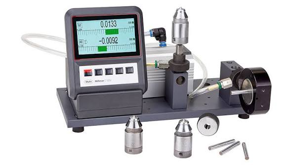
Overview
Air gaging measures dimension from the back pressure of air escaping between a set of jets and the workpiece. It is used at the point of manufacture for inside and outside diameters held to tenths. The same principle also measures form and feature relationships, including taper, ovality, lobing, straightness, squareness, flatness, center distance and match clearance. The jets don't touch the part, so readings don't depend on operator feel, and the airflow clears coolant and oil from the measuring area. That makes the method suitable for soft, polished and thin-walled parts.
A Mahr air gaging system is built from four components:
| Component | Function | Current products |
|---|---|---|
| Air tooling | Places the measuring jets against the feature | Dimensionair plugs, rings, snaps, jet probes, custom multi-circuit tooling |
| Measuring module | Converts the pneumatic signal to an electronic one; one module per air circuit | Millimar N 1701 PF modules (part of the N 1700 system) |
| Readout | Displays the deviation, classifies against tolerance, outputs data | Millimar µDimensionair II, C 1202, C 1750 PC, Cockpit software |
| Setting master | Sets zero (single master) or both tolerance limits (dual master) | Master rings, plugs and discs (AGD and DIN) |
Principle of operation
The pressure–distance curve
Air gaging works on a simple relationship: the smaller the gap between a jet and the workpiece, the higher the back pressure in the line. A garden hose shows the same effect. Hold your thumb well away from the nozzle and the water flows freely. Bring it closer and the pressure behind it builds. Cover the nozzle completely and the pressure stops rising. The useful part is in the middle, where each small movement of your thumb produces a clear, predictable change in pressure.
Plotting back pressure (vertical axis) against distance, the gap between jet and workpiece (horizontal axis), gives the pressure–distance curve. It has three distinct zones:
- Too close: the jet is nearly sealed and pressure sits close to the supply level. Further changes in the gap barely move the pressure, so the gage loses sensitivity.
- Measuring range: pressure changes in direct proportion to the gap. This straight section is where the gage is calibrated, and every reading is taken here.
- Too far: air escapes almost unrestricted and pressure approaches its minimum. Again, changes in the gap barely register.
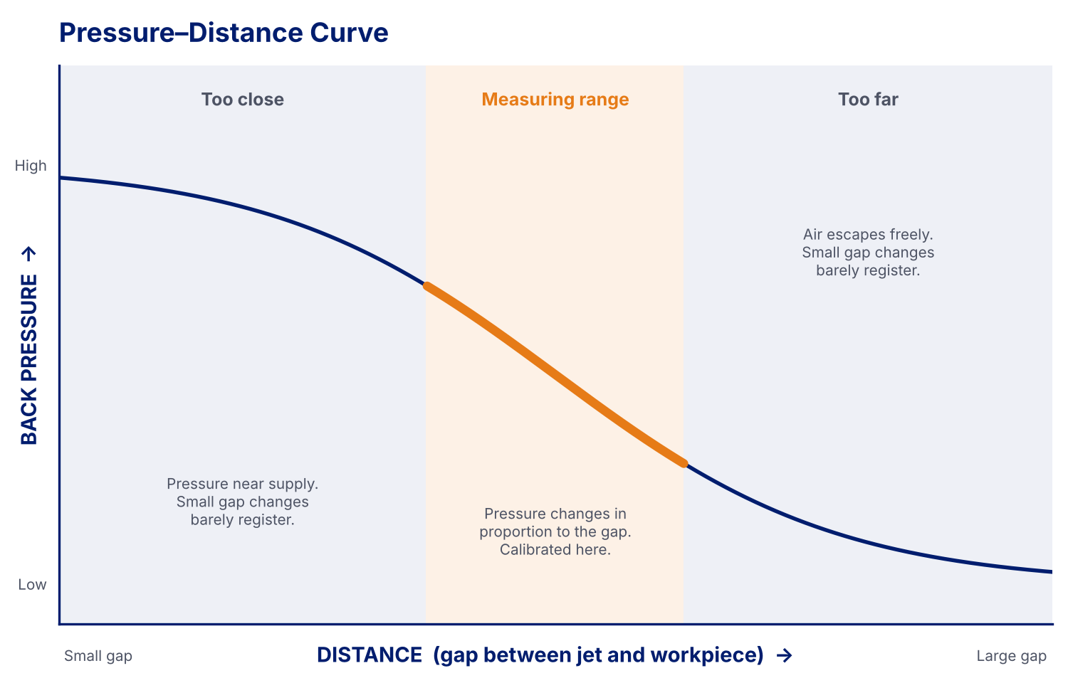
Air tooling is designed so that a part at nominal size puts the jets in the middle of that straight section. The part tolerance then has to fit inside it. That is why each tooling ID has a stated measuring range, and why tooling is selected by tolerance (see Tooling selection below). A part far enough out of tolerance pushes the jets out of the linear zone, and the reading is no longer proportional.
Mahr's Dimensionair system has a long linear section, so the plug can run with more clearance to the bore wall. The plug enters tapered, out-of-round or barrel-shaped bores more easily, the body wears less against the bore edge, and the jets can sit deeper in the plug body, where they are protected and less prone to clogging.
Balanced differential circuit
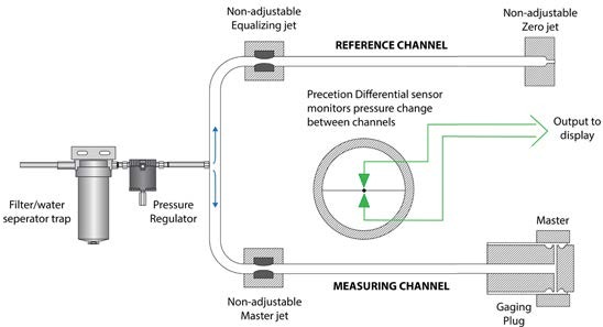
Regulated supply air divides into a reference channel and a measuring channel that ends at the gage jets. A differential sensor bridges the two channels. A change in supply pressure affects both channels equally and cancels out, so the reading moves only when workpiece size changes. Once set, zero does not drift with shop-air fluctuation.
Mastering: single and dual
Mahr's Dimensionair system is built around single-master setup with fixed magnification. All current Millimar readouts also support dual-master (min/max) setup, so the same readout can run Mahr tooling or two-master tooling from adjustable-magnification systems.
| Single master | Dual master (min/max) | |
|---|---|---|
| Masters per size | One, at nominal | Two, at the minimum and maximum limits |
| Magnification | Fixed by the tooling and readout | Calculated from the two masters |
| Setup | Place the master, press auto-zero. Master deviation can be entered. | The readout guides the operator through both masters and sets zero and magnification automatically. |
| Tooling | Mahr Dimensionair tooling of the matching ID; interchangeable without recalibration | Most two-master tooling, with jet sizes from about 0.020" to 0.050", via adaptors where needed |
| Typical use | Mahr Dimensionair systems; one master per size | Existing tooling from other air gage systems |
With fixed magnification, plug wear doesn't change the scale, and the tolerance limits stay the same from the first part of a shift to the last.
What air gaging measures
Diameter is the most common application. Jet placement, the number of circuits, and how the readout combines them extend the method to form and feature relationships. Dynamic functions (Max, Min, Max–Min) capture form while the part or tooling is rotated or moved.
| Characteristic | Tooling and method |
|---|---|
| Diameter (ID / OD) | Two-jet plug, ring or snap. Two-jet differential reading cancels radial play along the jet axis. |
| Taper, barrel, hourglass | Two-jet plug moved axially through the bore, reading the change in size |
| Taper angle and size | Multi-circuit taper plug or ring, two channels. Jam-fit tooling reads angle only. Shoulder-style tooling reads angle and size, with an optional third circuit for side straightness. |
| Ovality (even-number lobing) | Two-jet tooling rotated, Max–Min |
| Odd-number lobing | Three-jet plug or ring rotated. A two-jet reading can't detect it because the two-point diameter stays constant. |
| Average diameter | Four-jet tooling with a four-jet module |
| Straightness | Four-jet plug or ring rotated 180°, dynamic mode. It can be combined with a diameter circuit on a second channel. |
| Squareness, bore to face | Offset-jet plug square to a platen, part rotated 180°, Max–Min |
| Flatness, parallelism, thickness | Jet probe in a surface plate. A second, opposed probe adds thickness and parallelism. |
| Center distance | Paired two-jet plugs read differentially, independent of hole diameter |
| Match clearance | Air plug and air ring on two channels, reading clearance and both diameters |
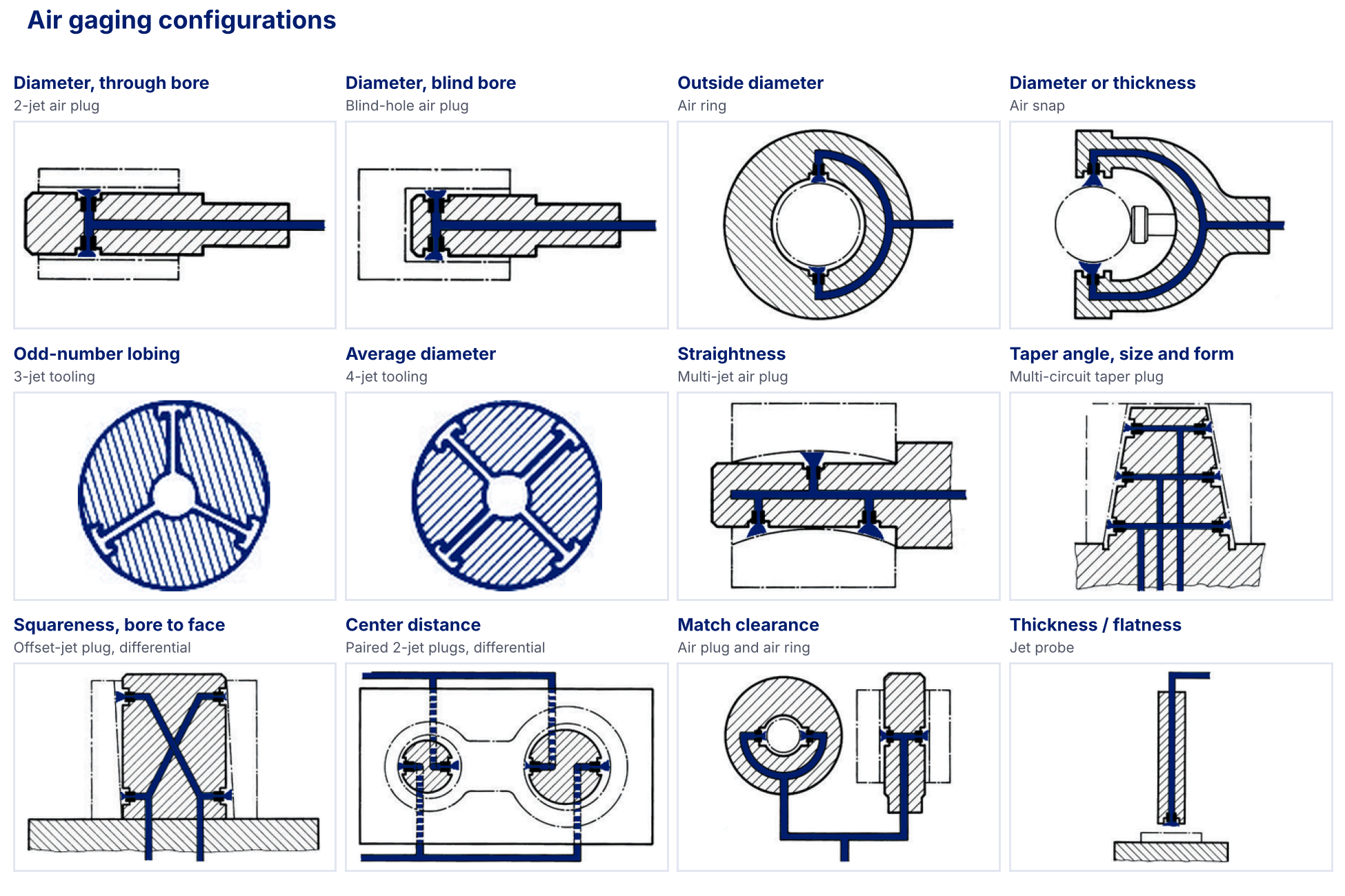
Mahr supplies taper tooling for standard machine tool tapers, including ISO 7388 and HSK holders.
Tooling selection
Tooling is selected by part tolerance. Each tooling ID has a fixed magnification and measuring range, and each has a maximum recommended surface finish.
| Part tolerance | Tooling | Magnification | Range | Max. finish (Ra) | Module |
|---|---|---|---|---|---|
| ±0.001" / ±25 µm | DP50 | 2500:1 | ±0.0015" | 50 µin | N 1701 PF 2500/5000 |
| ±0.0005" / ±13.5 µm | DP20 | 5000:1 | ±0.00075" | 20 µin | N 1701 PF 2500/5000 |
| ±0.0002" / ±5 µm | DP10 | 10,000:1 | ±0.0003" | 10 µin | N 1701 PF 10,000/20,000 |
| ±0.0001" / ±2.5 µm | DP5 | 20,000:1 | ±0.00015" | 5 µin | N 1701 PF 10,000/20,000 |
Where either DP50 or DP20 would work, DP20 gives less centralizing error below about 0.37". Low-magnification tooling costs less and is the default unless the bore requires high-magnification jets. On low-mag plugs under 0.248", use about two-thirds of the range for tolerance.
Surface finish
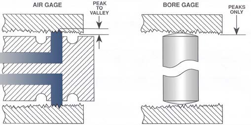
A jet reads across an area and fills surface valleys before back pressure builds. A contact gage rides only the peaks. On rough surfaces the two methods will disagree, so finish should be checked against tolerance before air tooling is specified.
Tooling styles
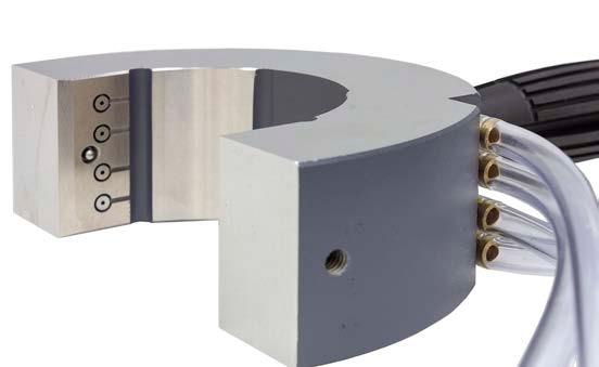
- Air plugs: through-hole, blind and super-blind. On super-blind plugs, the jet centerline sits as little as 0.045" from the plug end. Standard material is high-chrome stainless, and an AlCrN-based coating is available for high-wear applications.
- Air rings: two- and three-jet, 0.248" to 2" standard, with four- and six-jet for special applications. Through, shoulder and counterbore styles.
- Air snaps: 0.49" to 7.25" standard, for measuring ODs on centers or in the chuck.
- Jet probes: single or matched pairs, for flatness and fixture integration.
- Multi-circuit and custom tooling: several features in one placement, such as taper, multiple diameters, slots and partial bores. This includes tooling for automated and robot-loaded stations.
N 1700 measuring modules
The Millimar N 1700 series is a modular set of measuring electronics. Each module adds a measuring channel or a function, and modules connect to one another on a common RS-485 bus. Pneumatic, inductive and digital probe channels can be combined in one system. One to two N 1701 PF modules connect to the C 1202. For larger stations, the modules connect through an N 1701 USB module to the C 1750 PC or to Cockpit software on a Windows PC.
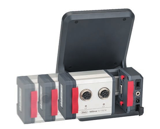
| Module | Function |
|---|---|
| N 1701 PF 2500/5000 | One pneumatic gage head, low-mag (50/20) tooling, 1-, 2- or 3-jet. Resolution to 0.1 µm / 5 µin. |
| N 1701 PF 2500/5000-4J | One pneumatic gage head, low-mag four-jet tooling |
| N 1701 PF 10,000/20,000 | One pneumatic gage head, high-mag (10/5) tooling |
| N 1701 PE-F | Extended-range tooling, such as pump barrel plugs, adapted to the range of the tooling |
| N 1702 M / N 1704 M | Two or four Mahr inductive probes |
| N 1702 VPP | Digital probes |
| N 1704 I/O | Four inputs and four outputs for control |
| N 1701 USB / N 1701 PS | PC connection / power supply |
Mahr also offers modules for third-party probes, including Marposs and TESA. One filter-regulator kit supplies up to three N 1701 PF modules.
Readouts
µDimensionair II
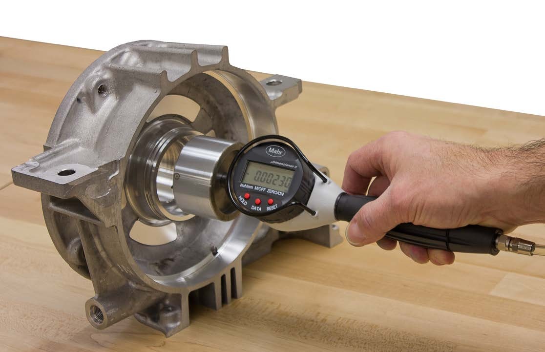
Portable, self-contained single-channel unit for handheld, bench or on-machine use. No module is required.
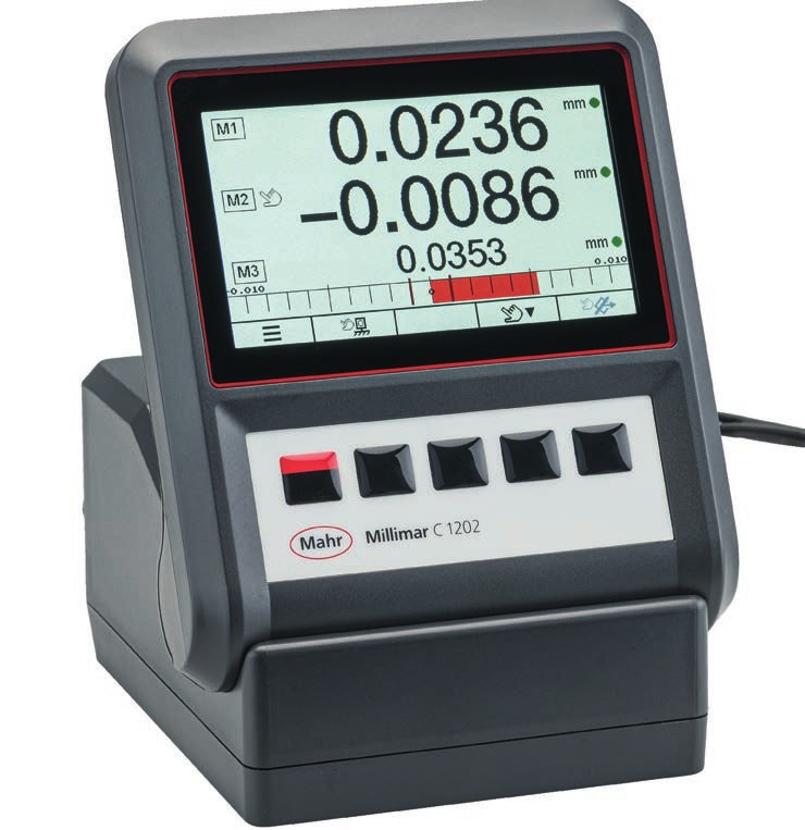
Millimar C 1202
Bench amplifier for one or two N 1701 modules. With two channels it reads taper angle, match clearance or two diameters at once.
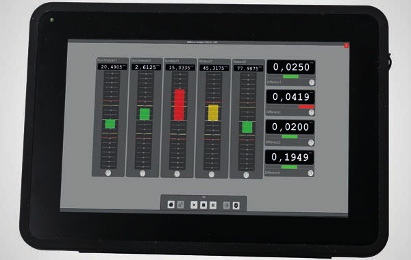
Millimar C 1750 PC
Touchscreen gaging computer running Millimar Cockpit, for multi-feature stations built from N 1700 modules.
| µDimensionair II | C 1202 | C 1750 PC | |
|---|---|---|---|
| Inputs | 1 pneumatic (built in) | 1–2 N 1701 modules | Up to 128 features via N 1700 modules |
| Display | Analog with 1-line digital | 4.3" color TFT | 10.1" touchscreen |
| Mastering | Single or min/max | Single or min/max | Nominal, max, min |
| Dynamic functions | Max, Min, Max–Min | Max, Min, Max–Min, (Max+Min)/2 | Max, Min, Max–Min, (Max+Min)/2, mean |
| Classification | 3 classes | 5 tolerances | Up to 20 classes |
| Data output | USB, RS-232, Digimatic, wireless | USB, Digimatic | USB, RS-232, RS-485, W-LAN; Excel and qs-STAT export |
| Power | Battery, approx. 3000 h | AC adapter | 100–240 V |
| Protection | IP54 | IP42 | IP65 (front panel) |
Millimar Cockpit is also available as software for a Windows PC. It includes preset formulas for common features, such as thickness, coaxiality, ovality, radial run-out, conicity and concentricity, along with a formula editor for custom combinations.
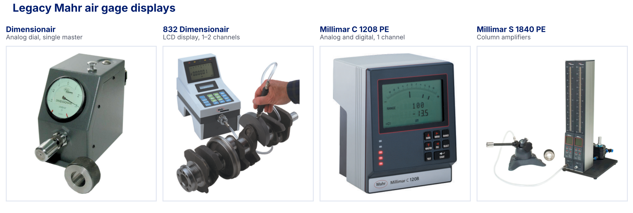
Upgrading legacy displays
Many shops still run Mahr air gages from earlier product generations. These displays are no longer in Mahr's current lineup, but the tooling built for them still is. Dimensionair plugs, rings and snaps carry over to the current Millimar readouts. Only the display and the pneumatic-to-electronic module change, so existing tooling and masters stay in service.
Specifying a system
Air tooling is made for the application, and tooling that was specified incorrectly isn't returnable. A complete specification includes:
- Nominal size, tolerance and surface finish
- Characteristics to be measured (size, form, relationships)
- Through, blind or counterbored, and the bore length
- Location of the check along the bore
- Part geometry and material
- Production volume, and whether gaging is manual or automated
- Readout and mastering method (single or dual master)
Order setting masters with the tooling. Mahr manufactures and certifies its own master rings, plugs and discs, and its calibration lab is accredited to ISO 17025 (NVLAP Lab Code 200605-0).
ICS reviews the part print against this checklist, recommends the tooling ID, jet configuration and modules, and plans the readout upgrade path for shops running legacy displays.
Mahr Inc.
With over 160 years of experience, Mahr is a global leader in precision metrology for quality control in measuring rooms, production, and development.
All Mahr Inc. lines →Questions about Air Gaging?
Tell us about your application and we'll point you to the right solution.