
MMQ - Formtesters
Mahr MarForm MMQ formtesters measure roundness, cylindricity and run-out to sub-micron accuracy. Compare the MMQ 100–500 and get specification help from ICS.
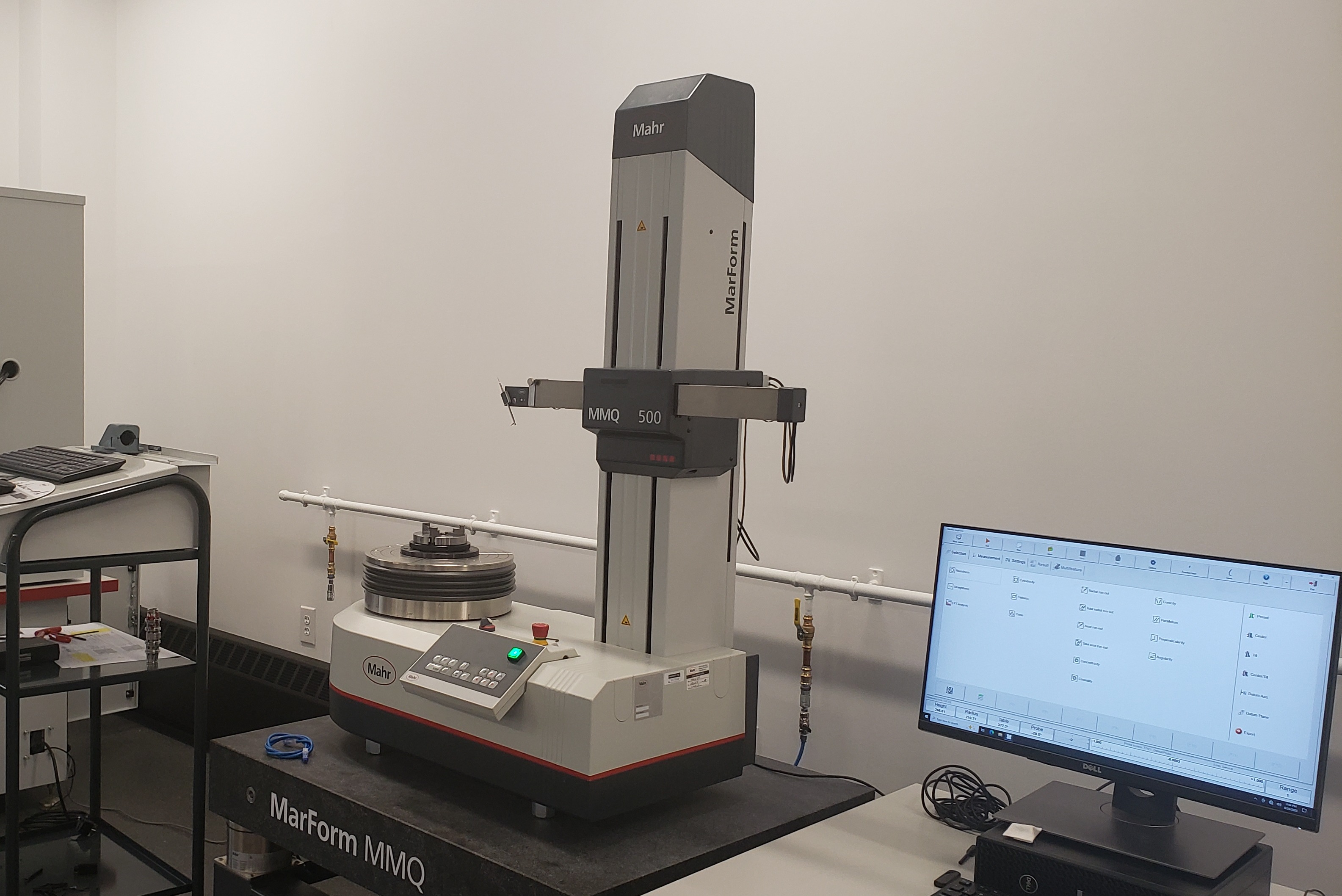
Size is not form
A bearing journal can measure at nominal with a micrometer at every angle and still be the reason a seal leaks or a bearing runs loud. Calipers, micrometers and bore gauges measure size between two points. Rotating parts fail on form: how far the surface wanders from a true circle, a straight line or a common axis. These are the form and position characteristics of GD&T, defined in ISO 1101 and ASME Y14.5.
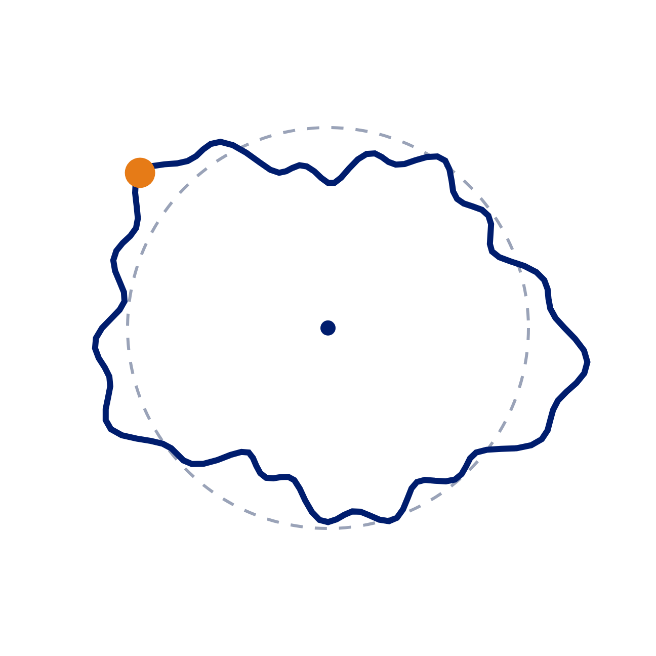
A part with an odd number of lobes is the classic blind spot. Its two-point width is the same in every direction, so a micrometer reads it as round. On a non-critical diameter that may not matter. In a hydraulic spool bore or under a lip seal, it does.
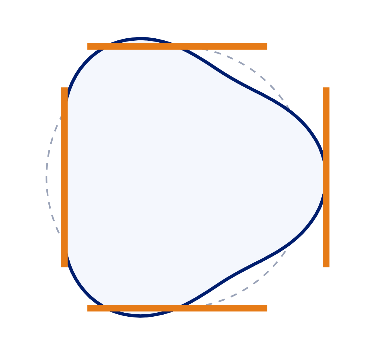
The lobing is exaggerated for clarity. Real deviations on precision parts are typically a few microns or less (≈ .0001" and below).
How a formtester measures
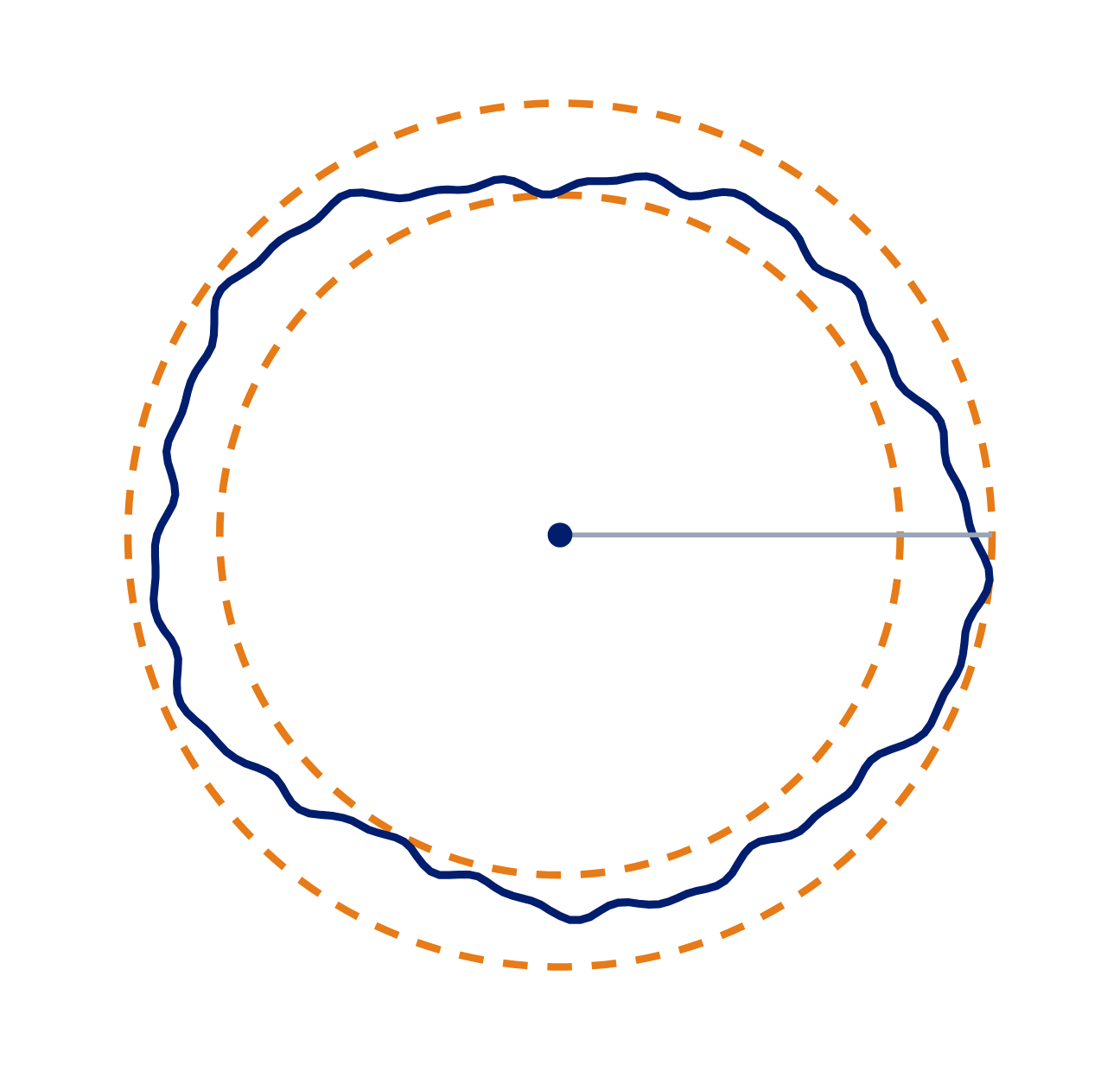
A formtester does not measure size. It detects deviation from a theoretically perfect form: a true circle, a straight line, a flat plane. The part sits on a precision rotary table, the C-axis, and a probe rests against the workpiece. As the part turns, the probe records its deflection thousands of times per revolution: how far the surface pushes the probe in or lets it out. The software plots those readings around a circle, greatly magnified, to produce a polar profile. A polar profile is a map of the part's cross-section in which high and low spots show up as bumps and dips on a ring. Because the probe only sees deviation, the spindle itself has to run truer than anything it is asked to measure, which is why spindle error is the first number on any formtester spec sheet.
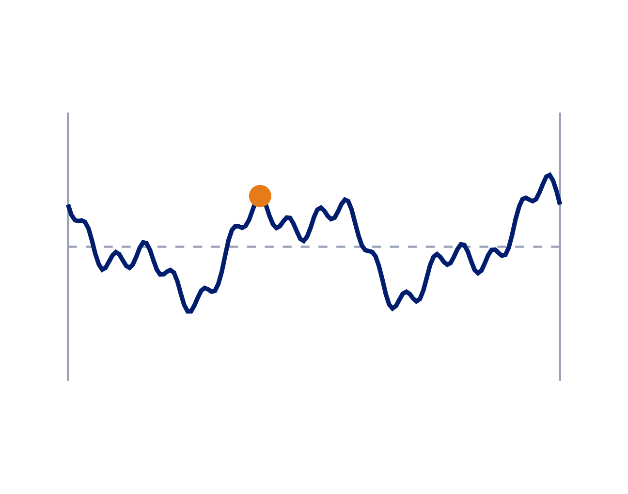
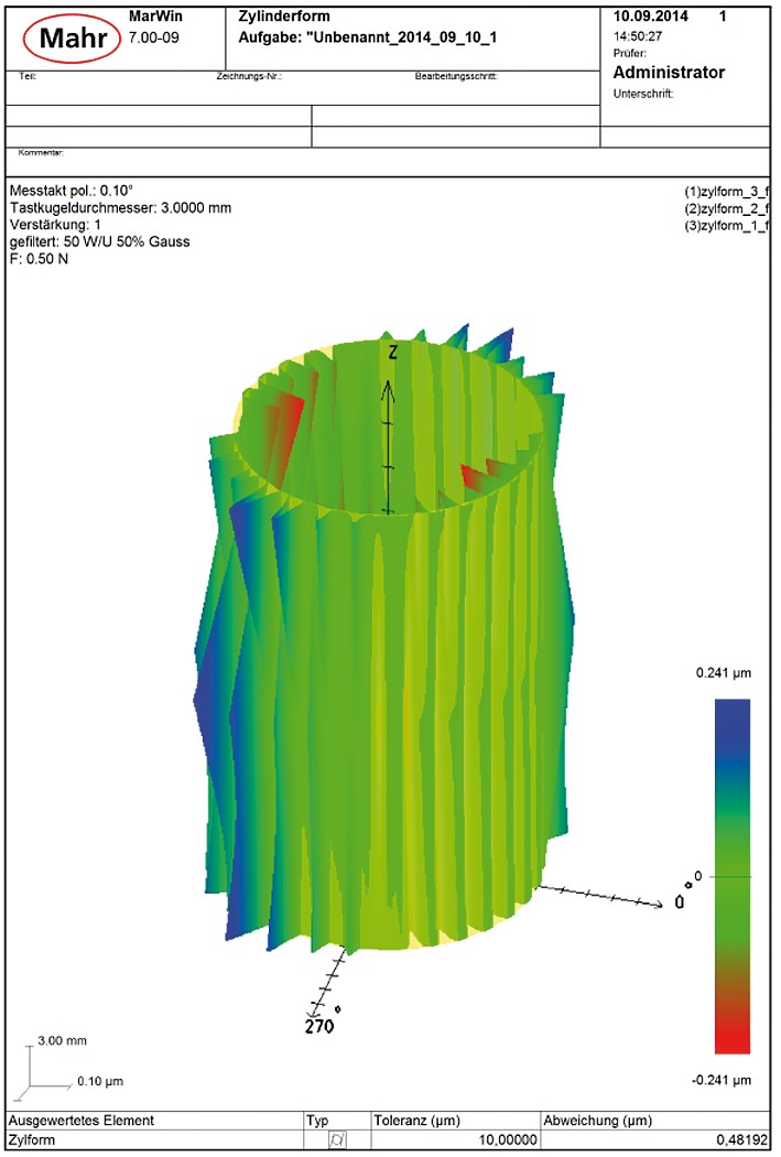
Add a vertical axis (Z) and a horizontal axis (X) that are straight and aligned to the spindle, and the machine can combine traces. Circles stacked at several heights give cylindricity and a datum axis. Traces running up the side give straightness and parallelism. Traces across a face give flatness and perpendicularity.
| Characteristic | How it is traced | What it protects |
|---|---|---|
| Roundness | One full circle on the C-axis | Seal contact, bearing fit, bore-to-spool clearance |
| Cylindricity | Several circles at different heights, or a helix | Taper and barreling along a journal or bore |
| Straightness and parallelism | Vertical (Z) traces along the generating line | Guide surfaces, plungers, piston skirts |
| Coaxiality and run-out | Circles referenced to a datum axis built from two other circles | Bearing seats on a common axis, shaft balance and vibration |
| Flatness and perpendicularity | Circles or X-axis traces across an end face | Thrust faces, mounting shoulders, sealing faces |
Getting from a trace to a number
The software fits a reference circle to the profile, usually least-squares (LSC) or minimum zone (MZC), and reports the radial gap between two concentric circles that enclose the profile. That fit also removes simple off-center mounting, so a part does not have to be perfectly centered to be measured. A filter, set in undulations per revolution (upr), decides what counts as form and what counts as surface texture. 15 upr is the common default for form, and 50, 150 or 500 upr let progressively finer waviness through. Two machines reporting the same part differently are often running different filters, so the filter belongs on the drawing or in the inspection plan.
When to choose a formtester
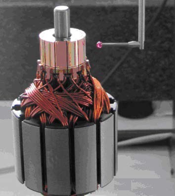
A formtester earns its place on a rotationally symmetric part whose function depends on running, sealing or fitting against a mating part. In practice the drawing then carries form or run-out tolerances of a few microns or less, and two-point gauges and point-sampling CMM routines can no longer resolve them. Typical parts include fuel-injection and hydraulic components, ABS and steering parts, gearbox and rotor shafts, bearing rings and rolling elements, pistons, camshafts, compressor parts, commutators and hip-joint implants. The trade-off is that a formtester measures deviation from ideal geometry, not size. It does not replace a bore gauge or a CMM for diameters, positions and prismatic features.
| Your application | Start with |
|---|---|
| Roundness, run-out or concentricity only, on parts up to Ø210 mm (≈ 8.3") | MMQ 100 |
| Cylindricity, straightness or total run-out on the print, with straightness tolerances above about 1 µm (≈ .00004") | MMQ 150 |
| Sub-micron cylindricity or straightness on compact parts up to Ø210 × 380 mm (≈ 8.3 × 15") | MMQ 200 with the T20W probe |
| The same compact parts, with bores, outside diameters and faces measured in one program without resetting the probe | MMQ 200 with the T7W probe |
| Shafts or housings taller than 250 mm (≈ 9.8"), up to 900 mm (≈ 35.4") | MMQ 400, with a Z column sized to the part |
| Shafts longer than 200 mm (≈ 7.9") that are best held between centers | MMQ 400 with the motorized tailstock |
| Face perpendicularity or flatness along a line, or contour, cam or piston evaluation | MMQ 400 (X measuring axis and evaluation options) |
| Heavier parts up to 80 kg (≈ 176 lb), or programs that need several probe arms changed automatically | MMQ 500 |
Limits. If the print controls only size, a bore gauge, micrometer or air gauge is faster and cheaper per part. Prismatic parts and feature positions belong on a CMM. The MMQ diameter option is rated for diameter tolerances of 20 µm (≈ .0008"), so it supplements size gauging rather than replacing precision diameter measurement.
Reading the profile
A formtester does more than pass or fail a part. The polar profile also shows what produced the error. Count the high spots around the circle, the undulations per revolution (upr), and the count usually points to a step in the process. The software does the counting with a Fourier analysis (FFT), which splits the profile into its wave counts and reports how tall each one is.
Reading an accuracy spec
Formtester spindle accuracy is written as a fixed term plus a term that grows with height above the table, for example 0.02 µm + 0.0005 µm/mm. The further the probe is from the bearing, the more any tilt in the rotation shows up. At 100 mm (≈ 4") above the table that example works out to 0.07 µm (≈ .0000028"), a calculated value.
A common convention is a 10:1 gage-to-tolerance ratio, which means the measuring system should be about ten times better than the tolerance it checks. Measured at 100 mm (≈ 4") above the table, the spindle error limits work out to 0.11 µm for the MMQ 100, 0.09 µm for the MMQ 150 and 200, and 0.07 µm for the MMQ 400 and 500. At 10:1, those support roundness tolerances of about 1.1 µm (≈ .000043"), 0.9 µm (≈ .000035") and 0.7 µm (≈ .000028") respectively. All of these figures are calculated, and they cover the spindle only. Setup, probe and stylus choice, and the room usually dominate real-world uncertainty, so treat them as a floor, not a guarantee. Published figures assume 20 °C ±1 °C (68 °F ±1.8 °F) and a vibration-free mount, so the bench and the location matter as much as the machine.
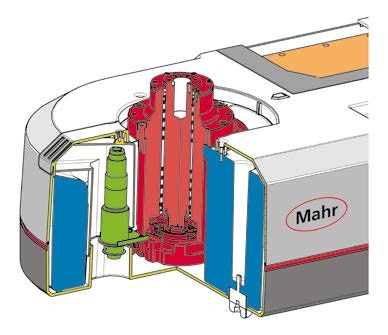
Why Mahr uses mechanical bearings
Many high-end roundness instruments float the spindle on air. Air bearings run very true but have low stiffness, so drive forces, uneven part loads and floor vibration can move the axis. The MMQ spindles run on precision balls in direct contact between rotor and stator, which Mahr rates at up to 70 times stiffer. The trade is a spindle that holds its accuracy outside a lab, with no compressed air supply to install or keep dry.
The MMQ range
All five machines share the same spindle concept and MarWin software. They differ in which axes are motorized, how large a part they take, and how much of the setup they do themselves.
MMQ 100
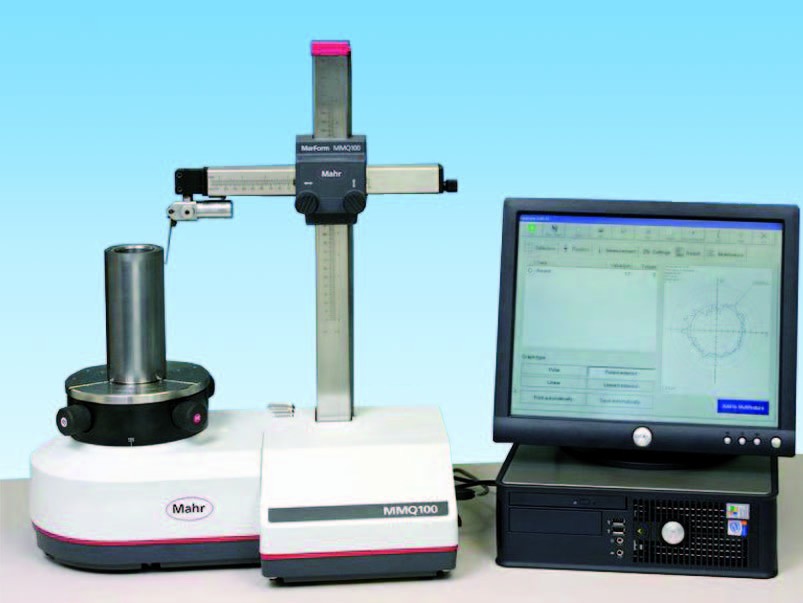
A compact, 28 kg station with manually positioned axes. Digital encoders on Z and X pass the axis position to the software, and EasyForm runs on a touchscreen. It measures from circular traces: roundness, run-out, concentricity, coaxiality and flatness from a circle.
Choose it when you need roundness and run-out checks, and cylindricity is not on the print.
MMQ 150
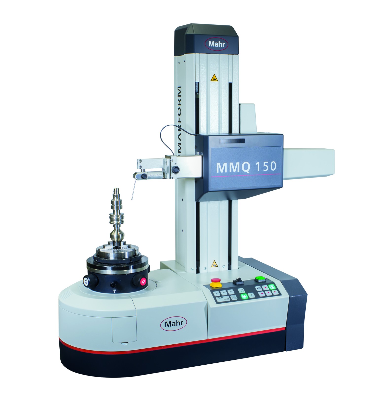
A motorized 250 mm Z measuring axis makes cylindricity, straightness and total run-out automatic. It has a manual centering and tilting table and the T20W probe, and takes parts up to Ø210 mm.
Choose it when you need cylindricity in production and your straightness tolerances are above about 1 µm (≈ .00004").
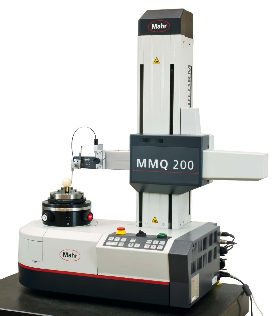
MMQ 200
Same footprint and volume as the MMQ 150, with a much straighter Z-axis: 0.3 µm (≈ .000012") over 250 mm against 1 µm. It also positions faster. The T7W version adds a motorized probe that sets its own contact angle, so one program can measure bores, outside diameters and both faces without the operator resetting the probe.
Choose it when the part is compact but the cylindricity or straightness tolerance is sub-micron.
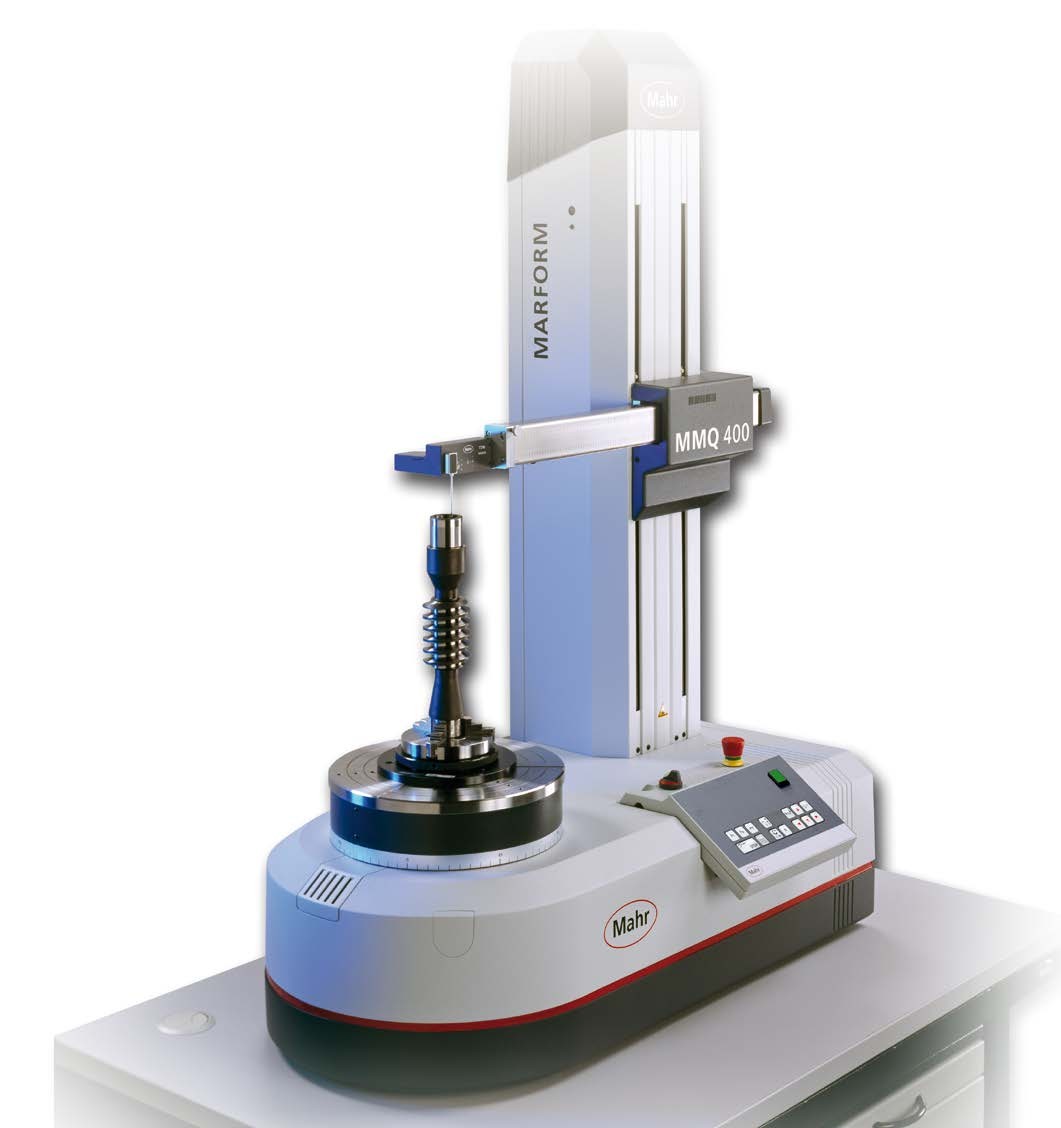
MMQ 400
A modular machine built to the application. Z is 350, 500 or 900 mm, with a manual or motorized centering and tilting table and a manual or motorized probe. A true X measuring axis adds perpendicularity and contour work. A motorized tailstock holds shafts longer than 200 mm between centers. The table carries up to 600 N, about 60 kg (≈ 132 lb), or 400 N, about 40 kg (≈ 88 lb), on the 900 mm column.
Choose it when the parts are long, tall or heavy, or you need contour, cam or piston evaluation on the same machine.
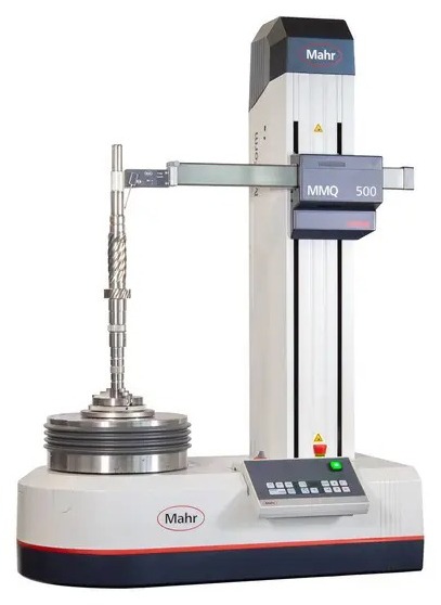
MMQ 500
An automatic Ø300 mm centering and tilting table aligns parts to 0.5 µm (≈ .00002") and carries up to 80 kg (≈ 176 lb). A four-arm probe unit changes styli without the operator. It takes parts up to Ø530 mm, with 470 mm of Z travel.
Choose it when parts weigh up to 80 kg (≈ 176 lb), or one program needs several probe arms changed automatically.
Narrowing it down
Spindle accuracy is close across the motorized machines. Three questions about the part separate them faster than a spec sheet:
- Does the print call out cylindricity, straightness or total run-out? If so, you need a motorized Z-axis, which rules out the MMQ 100.
- How big, long and heavy is the part? The MMQ 150 and 200 take parts up to Ø210 mm on a 200 N (≈ 45 lbf) table. Longer shafts and heavier housings move to the MMQ 400 or 500.
- Who does the setup? On the manual tables, the software tells the operator which screw to turn. The motorized tables on the MMQ 400 and 500 center and tilt the part themselves, and the motorized probes change direction or stylus mid-program.
Motorized Z measuring travel
Values are the motorized Z measuring path from Mahr's technical data. The MMQ 100 is not shown because its Z-axis is positioned by hand.
Beyond form
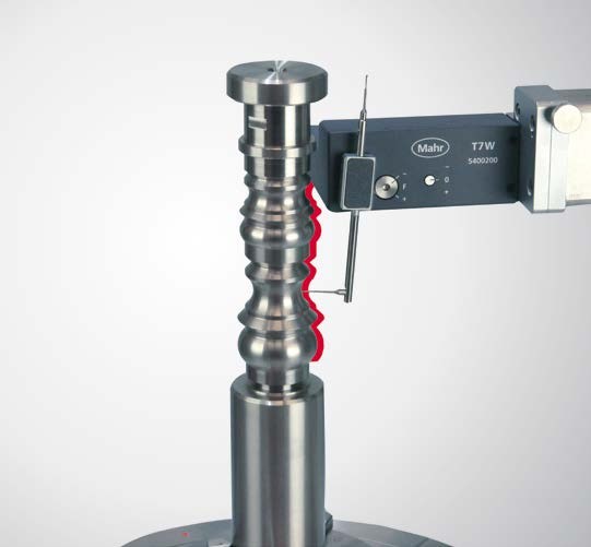
Once a part is centered on a precision spindle, other measurements are cheaper to take there than on a second instrument with a second setup. Depending on the model and probe, MarWin options add:
- Roughness: a skidded roughness pick-up mounted alongside the form probe, measured in the same run.
- Contour: radii, angles and distances traced with the Z and X axes, with path control on the MMQ 400.
- Lead (twist): macro lead on dynamic seal journals, evaluated to Mercedes-Benz standard MBN 31007-7.
- Dominant roundness waviness: periodic lobing on seal and bearing seats, evaluated to MBN 10455.
- Application packages: cam profiles, pistons, commutator bar-to-bar variation, and bearing vibration-velocity analysis.
Where ICS fits
ICS is a manufacturers' representative. Our job is matching the application to the right measuring tools. For a formtester, the selection is driven by:
- the form and run-out tolerances on the print, and the gage ratio you need to hold
- part diameter, length and weight against each machine's measuring volume and table load
- the evaluations required beyond form: roughness, contour, lead, cam or application packages
- where the machine will run, its temperature and vibration conditions, and who will operate it
- how results need to reach your SPC or quality system
From those inputs we recommend one measuring setup: the machine, table, probe, fixturing and software options. We also support the line in the field.
Mahr Inc.
With over 160 years of experience, Mahr is a global leader in precision metrology for quality control in measuring rooms, production, and development.
All Mahr Inc. lines →Questions about MMQ - Formtesters?
Tell us about your application and we'll point you to the right solution.